6 Common Types of Metal Forming Processes and Their Applications
From the cars we drive to the airplanes soaring above us, metal forming processes shape the world we live in.…
In the world of hydraulic and pneumatic systems, directional control valves play a pivotal role in managing fluid flow and ensuring efficient operation. These specialized components are essential for directing the movement of fluids, enabling machinery to perform a wide range of tasks. Whether you’re a seasoned engineer, a technician looking to deepen your understanding, or simply curious about how these valves function, grasping the various types of directional control valves and their applications can significantly enhance your knowledge of fluid power systems. In this article, we will explore six distinct types of directional control valves, highlighting their unique characteristics and uses. By the end, you’ll have a comprehensive understanding of how each type can be effectively employed in different scenarios, helping you make informed decisions for your projects. Let’s dive into the fascinating world of directional control valves!
Directional control valves (DCVs) are crucial components in hydraulic and pneumatic systems, as they manage the flow of fluids to control various mechanical movements. These valves are essential for directing fluid flow, which governs the operation of actuators, cylinders, and other system components. Understanding the different types of DCVs is vital for engineers, technicians, and anyone involved in fluid power systems. This knowledge helps in both designing new systems and maintaining existing ones.
DCVs act as the command center of fluid systems, providing precise control over fluid movement and pressure. By controlling fluid flow direction, DCVs enable mechanical processes such as lifting, pressing, and moving objects in various industries. The reliability and efficiency of these valves directly affect the performance and safety of systems.
This article provides a detailed guide to the various types of directional control valves, explaining their functions and applications. Whether you are designing a new system or troubleshooting an existing one, understanding DCVs is essential for optimizing performance. By exploring the different types of DCVs, readers will gain valuable insights into their operation, helping them effectively utilize these valves in various industrial applications.
Two-way directional control valves are the simplest type of DCVs. They have two ports and allow fluid flow in one direction. These valves come in two configurations:
Applications: Two-way valves are commonly used in basic pneumatic systems for simple on/off control, such as air compressors and actuators.
Three-way directional control valves can divert fluid flow between two different paths. They have one inlet and two outlets, enabling them to direct flow to one outlet while blocking the other.
Applications: Three-way valves are often used in systems that need to redirect fluid flow, such as pneumatic cylinders controlling extension and retraction.
Four-way directional control valves are designed to control double-acting cylinders or actuators. They feature two inlet ports and two outlet ports.
Applications: Four-way valves are common in complex pneumatic systems, such as automated conveyor systems and robotics, where precise control over multiple actuators is required.
5/2 valves have five ports and two positions, making them effective for controlling double-acting cylinders. They can connect to both the extend and retract sides of a cylinder, providing a means to exhaust or vent the fluid effectively.
Applications: These valves are commonly used in applications that require straightforward control over double-acting cylinders, such as assembly lines.
5/3 valves feature three positions and five ports, allowing for more complex control scenarios. They can handle different flow paths and incorporate additional exhaust options.
Applications: These valves are suitable for applications requiring precise control and multiple functions, such as machines managing flow direction and pressure simultaneously.
Selecting the right directional control valve is crucial for the efficient operation of hydraulic and pneumatic systems.
Two-way directional control valves are crucial components in hydraulic and pneumatic systems, controlling fluid flow through two ports with straightforward on/off functionality. These valves are essential for managing fluid dynamics effectively in various applications.
There are two primary configurations for these valves: Normally Open (NO) and Normally Closed (NC).
These valves provide basic on/off control, either allowing or blocking fluid flow based on the valve’s position. This binary operation is fundamental for applications requiring simple flow management.
Two-way directional control valves are ideal for basic on/off control in various systems, such as blow-off devices and fluid motors operating in one direction. While two-way valves alone can’t cycle a single-acting cylinder, pairs of these valves can be configured to control more complex systems, like double-acting cylinders, enhancing their utility.
Although two-way valves are effective for basic tasks, they lack the versatility of three-way and four-way valves. The latter can direct fluid between multiple paths and control more complex actuators, making them suitable for advanced applications.
Two-way directional control valves offer essential on/off control with two ports, making them ideal for simple applications. However, they are less versatile compared to other valves, which provide more advanced control features for complex systems.
Three-way directional control valves are crucial components in fluid power systems, featuring three ports: an inlet, an outlet, and an exhaust port. These valves control the flow of fluid to an actuator and allow the fluid to return from it. They come in various configurations and actuation methods, such as solenoids, levers, and cams, with solenoid-operated three-way valves being particularly common. These are typically represented as 3-way, 2-position valves, where the activation of the solenoid changes the flow path between the ports.
The operation of three-way directional control valves is straightforward yet highly effective: when the solenoid is de-energized, the valve allows fluid to flow from the inlet to the exhaust port, and when energized, it redirects the flow from the inlet to the outlet port. This functionality is especially useful for single-acting cylinders, extending the cylinder when energized and retracting it when de-energized.
Three-way valves are versatile and employed in a wide range of applications:
Three-way directional control valves offer several advantages, including simplified control, versatility, and efficiency, making them valuable in various industrial applications.
These valves are essential in hydraulic and pneumatic actuators, automated machinery, and process control systems, ensuring precise and reliable performance.
Four-way directional control valves manage fluid flow for double-acting actuators, enabling both extension and retraction. These valves have four ports: two for the inlet and two for the outlet, allowing control of fluid to and from the actuator.
Four-way directional control valves are used in various applications, particularly where precise control of double-acting actuators is required:
Four-way valves can be operated in different ways, each suited to specific applications:
When selecting four-way directional control valves, consider the following factors:
Regular maintenance is crucial for the reliability and longevity of four-way directional control valves. Important practices include:
If issues arise, focus on common problems like sticking valves, improper actuation, or fluid leaks, which can often be resolved through simple adjustments or component replacements.
5/2 valves are directional control valves with five ports and two positions, used to control double-acting cylinders. In one position, the valve directs fluid to extend the cylinder while exhausting fluid from the retract side, and in the other position, it reverses the flow. These valves are commonly used in assembly lines for straightforward actuator control.
5/3 valves have three positions and five ports, offering more control options and exhaust paths than 5/2 valves. In one position, the valve connects the inlet to one outlet and vents the other; in the second position, it reverses the flow; and in the central position, it can block flow or allow exhaust from both sides. These valves are ideal for pneumatic systems needing sophisticated control, like managing pressure and flow direction simultaneously.
Poppet valves use a disc or cone to control fluid flow, providing reliable pressure and flow management. Direct-acting poppet valves operate without pilot pressure, making them suitable for high-pressure applications with minimal leakage and quick response times. Pilot-operated poppet valves, controlled by external pilot pressure, offer enhanced control and versatility.
Check valves allow fluid flow in one direction only, preventing backflow and protecting system integrity. These valves open for fluid flow in the permitted direction and close to block reverse flow, using a ball or disc mechanism. They are essential in applications like pumps and hydraulic circuits where backflow can cause damage.
Shuttle valves enable fluid flow from two different sources, switching based on pressure differences. They select the higher pressure source to ensure continuous operation from the most effective source, making them useful in hydraulic systems requiring redundancy for reliability and uninterrupted operation.
Center positions in directional control valves (DCVs) determine the valve’s status when it’s not being used, affecting fluid flow through the system. Different center positions are suited for various applications:
In an open center configuration, all ports are interconnected when the valve is in its neutral position, allowing fluid to flow freely and enabling multiple actuators to operate simultaneously without restriction. This setup is commonly used in systems where continuous flow is necessary, such as in certain hydraulic circuits.
Closed center valves block all ports in the neutral position, stopping any fluid flow. This design is useful in systems with multiple actuators, as it allows each one to operate independently. It is often used in applications where maintaining pressure is critical, such as in hydraulic systems that require precise control without unintended movement.
Tandem center valves block two ports while connecting the other two. This allows pump flow to return to the tank without triggering the relief valve, which is useful in simple press circuits to manage pump flow and prevent overpressure situations.
In a float center configuration, one port is blocked while the other three are connected. This lets fluid return to the tank while isolating the pump, beneficial for applications where the actuator needs to move freely without pump pressure, such as in hydraulic systems controlling the movement of heavy loads.
The actuation method of a directional control valve determines how the valve is engaged or disengaged, impacting its response time, reliability, and suitability for various applications. The primary actuation methods include:
Manual actuation uses levers, knobs, or pedals to control the valve, offering simplicity and reliability. It’s ideal for tasks needing direct operator control, like maintenance or smaller systems.
Solenoid actuation uses electromagnetic solenoids to control valve positions remotely. It’s common in automated systems for quick, precise control but may struggle with high-flow applications where the electromagnetic force isn’t strong enough.
Hydraulic actuation uses hydraulic pressure to move the valve spool. This method provides smooth, precise control, making it perfect for applications needing accurate fluid management, such as heavy machinery.
Pilot-operated actuation uses a pilot pressure signal to control the valve spool, ideal for larger valves where direct actuation is impractical. It provides enhanced control and is reliable in high-pressure systems, ensuring dependable operation even under demanding conditions.
Mechanical actuation uses cams or rollers to move the valve spool, suitable for applications where mechanical control is preferred, offering a robust solution in environments where electrical control isn’t feasible.
In an open center configuration, when the valve is in the neutral position, all ports are connected, allowing fluid to flow freely from the pump to the tank. This setup is used in systems where only one actuator operates at a time, such as in hydraulic systems with fixed displacement pumps, ensuring fluid can circulate freely.
Closed center valves block all ports when in the neutral position, stopping fluid flow. This design is useful in systems with multiple actuators that need independent operation, often seen in hydraulic systems with pressure-compensated pumps.
Tandem center valves block two ports while connecting the other two when in the neutral position. This allows the pump’s flow to return to the tank directly, without using a relief valve. Tandem center valves are commonly employed in simple press circuits, where it is essential to maintain the position of a piston within a cylinder while still allowing fluid flow redirection back to the reservoir.
Float center valves block one port and connect the other three, allowing the actuator to move freely. In this setup, the pump port is isolated, and the work ports are connected to the tank. This design is ideal for applications where actuators need to follow the movement of a load without resistance from the hydraulic system.
Regenerative center valves let fluid flow from the outlet back to the inlet when in the neutral position. This increases actuator speed and energy efficiency by reducing the need for extra power, making it useful for quick cylinder extension.
Choosing the right center position for a directional control valve is crucial for your system. Consider the number of actuators, type of pump, and desired fluid flow patterns when selecting a center position. Each center position has distinct advantages tailored to meet the operational needs of various applications, ensuring efficient and reliable performance in fluid control systems.
Manual actuation uses levers, knobs, buttons, or pedals to control a valve’s position. This method is simple and reliable, ideal for direct operator intervention.
Solenoid actuation uses electromagnetic solenoids for valve control, enabling remote and automated operation.
Hydraulic actuation uses hydraulic pressure to move valves, providing smooth and precise control.
Mechanical actuation uses linkages like cams and rollers to move valves, ideal for machinery with synchronized operations.
Pilot-operated actuation uses pilot pressure to control valves, effective for high-force requirements.
Pneumatic actuation uses compressed air for valve control, ideal where electrical or hydraulic methods aren’t feasible.
Directional control valves (DCVs) are vital components in hydraulic and pneumatic systems, using a spool-type design to direct fluid flow efficiently. The spool is a cylindrical component that moves within the valve body to control fluid direction, and its position determines which ports are connected or blocked.
The spool has raised sections called lands that block fluid flow and recessed areas called undercuts that allow fluid to pass. The precision of these lands and undercuts is crucial for the valve’s performance, ensuring a perfect seal to prevent leaks and maintain efficient fluid control.
The valve body, typically made from durable materials like cast iron, steel, or aluminum, is precision-machined to house the spool accurately. This ensures smooth movement and reliable operation, with finely finished interior surfaces to minimize friction and wear, extending the valve’s lifespan.
DCVs can be actuated in several ways: manually with levers or knobs, mechanically with cams or rollers, electrically with solenoids, or using a smaller pilot valve to control the main spool’s movement. Each actuation method requires specific design considerations to accommodate the actuating force and movement.
Seals and gaskets, made from materials like rubber or PTFE, prevent fluid leaks and maintain pressure. Proper sealing ensures efficient valve operation and reduces the risk of contamination.
Ports are the valve’s entry and exit points for fluid, designed to connect securely with system piping or hoses. Common port types include threaded for smaller systems, flanged for high-pressure applications, and cartridge for modular systems, allowing easy replacement and maintenance.
Graphic symbols represent DCVs on schematics, using arrows for fluid direction, boxes for valve positions, and lines for port connections. Understanding these symbols is essential for system design and troubleshooting.
In summary, DCVs consist of a precision-machined spool and casing, various actuation mechanisms, seals and gaskets, ports, and standardized graphic symbols. Each component ensures efficient and reliable valve operation within hydraulic and pneumatic systems.
Spool-type design is crucial for directional control valves (DCVs) used in hydraulic and pneumatic systems. This design allows for precise control over fluid flow, making it integral to the functionality and efficiency of these systems.
At the heart of the spool-type design is the spool itself, a cylindrical component that moves within a precisely machined bore in the valve body. The spool features lands (raised sections) and undercuts (recessed sections), which work together to direct fluid flow by opening and closing various flow paths between the valve ports.
The valve body, usually made from cast iron, steel, or aluminum, is precisely machined to house the spool. This ensures smooth movement and reliable operation.
Spool-type valves operate by shifting the spool within the bore to connect or block different ports, thereby controlling the direction and flow rate of the fluid.
Spool-type directional control valves are used in mobile hydraulics, industrial machinery, machine tools, and hydraulic motors. They handle the demands of mobile systems, control actuators in industrial applications, manage small flow rates in machine tools, and control the direction and speed of hydraulic motors.
Spool-type valves offer precise fluid control due to their small radial clearance and precision machining. Their versatility allows them to be tailored to specific needs, and their robust design ensures long-lasting reliability even in demanding conditions.
In conclusion, the spool-type design in directional control valves plays a pivotal role in managing fluid flow in hydraulic and pneumatic systems. Its precision, versatility, and reliability make it indispensable in a wide array of industrial applications.
Graphic symbols are crucial for depicting directional control valves (DCVs) in fluid power systems. These standardized symbols ensure clarity and consistency in system design and troubleshooting by providing a universal way to communicate the function and configuration of valves on schematics and diagrams.
The International Organization for Standardization (ISO) has created standards for these symbols, specifically ISO 1219-1 and ISO 1219-2, to ensure they are understood correctly across various applications.
Squares and rectangles in valve symbols indicate different operational positions of the valve. For example, a two-position valve will have two squares.
Arrows show the direction of fluid flow within the valve, while solid lines represent the fluid paths when the valve is in a specific position.
Ports are labeled with letters or numbers to show where fluid enters and exits the valve. Common labels include P (pressure), A and B (actuator ports), and T (tank).
Represented by two squares with a line connecting them, indicating open and closed positions. A spring symbol may show the default position. Used for simple on/off control.
Shown with three ports (P, A, T) and two squares. Arrows and lines indicate flow paths for each position. Used for diverting flow or controlling single-acting cylinders.
Depicted with four ports (P, A, B, T) and two squares. Lines and arrows show fluid direction to double-acting actuators. Used for controlling double-acting cylinders.
Illustrated with four ports and three squares, each representing different center positions such as open, closed, tandem, or float. Used in complex circuits requiring flexible control.
Specialized valves include pilot-operated valves, which feature a dashed line for the pilot pressure line and arrows or triangles for hydraulic pilots, used in high-flow applications. Proportional valves, indicated by arrows through solenoids or lines on either side of the spool section, are used for precise control in servo systems. Mechanically actuated valves, represented by mechanical actuation methods like levers or rollers, are used when electrical or hydraulic actuation isn’t feasible.
Grasping these graphic symbols is essential for anyone involved in fluid power systems, as they provide a universal language that ensures clear communication, reduces errors, and enhances overall system efficiency.
Directional control valves (DCVs) are crucial in manufacturing processes, particularly in automated systems, as they control the movement of actuators and cylinders that perform tasks such as assembly, packaging, and material handling.
In the automotive industry, DCVs are essential for controlling hydraulic systems in vehicles, enabling precise operation and enhancing safety.
Aerospace applications require stringent standards for precision and reliability, making DCVs vital for hydraulic systems in aircraft.
In construction and heavy machinery, DCVs are integral for controlling hydraulic functions that power various equipment.
The agricultural sector utilizes DCVs to enhance the efficiency of farming operations through improved control of machinery.
In the oil and gas sector, DCVs are essential for managing fluid flow in extraction and processing operations.
DCVs are also widely used in the food and beverage industry, where hygiene and precision are paramount.
In the pharmaceutical sector, DCVs contribute to the safe and efficient manufacturing of medications.
Directional control valves (DCVs) are crucial in automated manufacturing systems, as they manage the movement and operation of various actuators and cylinders. These valves ensure that machinery operates efficiently and accurately, enhancing overall production processes.
In assembly lines, DCVs are integral to the functioning of robotic arms and automated equipment. They facilitate the precise movement of components, ensuring that each part is assembled consistently. Similarly, in packaging systems, DCVs ensure the precise operation of machinery used for filling, sealing, and labeling products. This precision not only maintains consistent packaging quality but also speeds up production lines, contributing to higher efficiency and reduced errors.
DCVs are essential in machining and fabrication processes, regulating the operation of machine tools and equipment. These valves play a vital role in hydraulic presses and CNC machines, which are pivotal in shaping and assembling metal components.
DCVs control hydraulic presses, ensuring they apply the correct force to shape metal parts accurately. This capability is crucial for producing high-quality components. In CNC machines, DCVs manage the movement of cutting tools and workpieces, allowing for precise machining of parts to exact specifications. The accurate control of fluid flow is essential for achieving tight tolerances and high-quality outputs in fabrication.
In quality control and inspection, DCVs are indispensable for ensuring product integrity. They control the positioning of sensors and cameras in automated inspection systems, allowing for accurate and efficient checks for defects or inconsistencies in products. This capability ensures that only high-quality items proceed to the next stage of production, reducing waste and enhancing overall quality.
The advantages of incorporating DCVs into manufacturing processes are significant. These include increased efficiency through reduced manual intervention, enhanced precision in machinery operation, minimized downtime due to lower error rates, and improved safety by maintaining controlled operating conditions. By leveraging the capabilities of DCVs, manufacturers can optimize their operations and achieve superior results.
Directional control valves (DCVs) are essential in automotive systems, managing hydraulic and pneumatic functions crucial for vehicle operation. These valves ensure precise fluid movement, which is vital for vehicle performance and safety.
DCVs are key components in hydraulic braking systems, controlling brake fluid flow to the calipers. Precise valve actuation allows for effective braking force, ensuring reliable vehicle response when brakes are applied. Modern vehicles often use solenoid-operated valves for enhanced responsiveness and ABS features.
In automatic and semi-automatic transmissions, DCVs control hydraulic fluid flow for smooth gear shifts. These valves manage pressure application to clutches and bands, enabling efficient power transfer from the engine to the wheels. Using 5/2 and 5/3 valves allows for complex control, improving drivability and fuel efficiency.
DCVs in power steering systems control hydraulic fluid flow to assist in steering. These valves provide variable assistance based on steering input, enhancing comfort and maneuverability. By adjusting fluid flow, DCVs ensure quick and precise steering response.
In air or active suspension systems, DCVs manage air or hydraulic fluid flow to adjust ride height and firmness. This allows for better handling, comfort, and adaptability to different load conditions. Three-way or four-way valves enable dynamic suspension adjustments based on driving conditions.
DCVs control coolant flow through the radiator and engine block to maintain optimal engine temperatures. This prevents overheating and ensures efficient engine performance, which is especially important in high-performance vehicles.
In some fuel injection systems, DCVs manage fuel flow to the injectors, controlling the timing and amount of fuel delivered to the engine. This improves engine performance, fuel efficiency, and emissions control. Solenoid-actuated valves enable rapid response and precise fuel delivery in modern systems.
These applications highlight the versatility and importance of directional control valves in the automotive industry, ensuring vehicles operate safely, efficiently, and comfortably.
Directional control valves (DCVs) play a crucial role in aerospace applications by ensuring precise and reliable control of hydraulic and pneumatic systems. Their ability to manage fluid flow and direction is critical for the safe and efficient operation of various aircraft components.
Two-way directional control valves have two ports and operate in a simple on/off manner, configured as Normally Open (NO) or Normally Closed (NC). Three-way directional control valves feature three ports and can direct fluid flow between different paths or block flow entirely.
Four-way directional control valves have four or five ports and are designed to manage double-acting cylinders and actuators.
Spool valves use a cylindrical spool that slides to control fluid pathways and can be configured in various ways.
Rotary valves use rotary motion to manage fluid flow, often through a rotating spool or cylinder.
5/2 valves have five ports and two positions, while 5/3 valves have five ports and three positions.
DCVs are critical in aerospace due to the stringent requirements for reliability, precision, and durability. These valves are designed to endure extreme conditions, including high pressures and temperatures, while ensuring the smooth operation of aircraft systems. Choosing the right DCV is essential, as any failure could have serious safety implications.
Aerospace DCVs must be designed to endure harsh conditions and maintain functionality over long periods without failure. This includes resistance to high temperatures, pressure fluctuations, and potential contamination.
The ability to precisely control fluid flow and direction is essential in aerospace applications. DCVs must provide accurate and responsive control to ensure the proper operation of flight control surfaces, landing gear, and other critical systems.
Regular maintenance and inspection of DCVs are vital to ensure their continued performance and reliability. Aerospace systems often have strict maintenance schedules and protocols to detect and address any potential issues before they lead to failure.
In summary, DCVs are fundamental to the safety and performance of aerospace systems, ensuring that aircraft operate efficiently and reliably under demanding conditions.
Leakage around the ports or valve body is a common problem with directional control valves (DCVs), which can reduce system efficiency and cause damage.
Valves may stick due to debris, corrosion, or mechanical wear, causing them to fail to switch positions effectively.
If a valve does not actuate correctly, it can lead to improper fluid flow and system malfunction.
Incorrectly connected ports can cause cross-connection issues, leading to improper fluid flow.
For valves with multiple positions, the intermediate position might not function correctly, leading to unintended movements.
Regular maintenance is vital for DCVs’ longevity and performance.
Follow the manufacturer’s guidelines for proper installation.
Match the DCV to the system’s pressure, flow rate, and fluid type.
Effective DCV operation requires proper training and documentation.
Below are answers to some frequently asked questions:
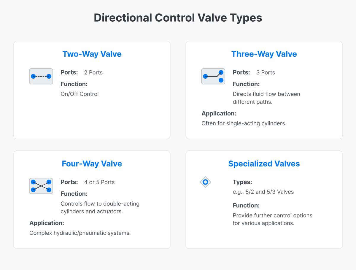
The main types of directional control valves (DCVs) include Two-Way, Three-Way, and Four-Way valves. Two-Way valves have two ports and function as on/off controls. Three-Way valves feature three ports and are used to direct fluid flow between different paths, often for single-acting cylinders. Four-Way valves, which have four or five ports, control the flow to double-acting cylinders and actuators, enabling more complex operations in hydraulic and pneumatic systems. Additionally, there are specialized types such as 5/2 and 5/3 valves that provide further control options for various applications.
Two-way valves have two ports: an inlet and an outlet. They function as simple on/off switches, allowing or stopping fluid flow entirely, and are commonly used in basic pneumatic systems for straightforward flow control.
Three-way valves have three ports and can direct fluid flow between different paths. They can act as diverting valves, directing flow from one port to another, or as mixing valves, combining fluids from two ports into one. These are used in systems requiring the diversion or mixing of fluid flow.
Four-way valves have four ports and are designed to control double-acting cylinders and actuators. The spool inside the valve can move to different positions to direct fluid flow through various paths, making them suitable for complex pneumatic systems and applications requiring precise control, such as automated conveyor systems.
Normally closed (NC) valves are designed to block fluid flow in their de-energized state, allowing flow only when energized. They are commonly used in applications where safety is paramount, such as emergency systems, ensuring that flow stops by default. Conversely, normally open (NO) valves allow fluid to flow continuously when de-energized, only closing when energized. NO valves are suitable for systems that require continuous flow, such as cooling and ventilation systems. The choice between NO and NC valves affects operational efficiency, safety, and control, making it crucial to select the appropriate type based on the specific needs of the application.
Directional Control Valves (DCVs) can be actuated through various methods, each suited to different applications and requirements. Manual actuation involves shifting the spool using a handle, button, or foot pedal, making it ideal for systems with infrequent adjustments. Mechanical actuation uses linkages such as cams and rollers to move the spool, suitable for applications where valve operation is tied to mechanical movements. Solenoid-operated actuation uses an electric coil to generate a magnetic force that shifts the spool, providing quick and easy control, commonly used in automated systems but requiring sufficient electrical power for high-flow applications. Pilot-operated actuation employs pilot pressure to move the spool, offering precise control, particularly in hydraulic and pneumatic systems. Each actuation method provides unique advantages, allowing for optimal performance in various industrial applications.
5/2 valves are primarily used for controlling double-acting cylinders, allowing for full control over both extension and retraction. They feature two positions with five ports: two for supply and working air, two for cylinder ports, and one for exhaust. These valves are ideal for high-speed applications like packaging and sorting systems, as well as precision applications such as robotics, due to their ability to independently control exhaust rates.
5/3 valves, on the other hand, have an additional neutral or middle position, providing more control flexibility. This neutral position can be configured in three ways: all ports blocked (APB) for locking the cylinder in place, center open to exhaust (COE) for isolating the mains supply, and center open to pressure (COP) for maintaining pressure in the cylinder. These configurations make 5/3 valves suitable for safety-critical applications, such as emergency stop scenarios or maintaining specific states when no actuation signals are present. Both 5/2 and 5/3 valves are extensively used in industrial automation and applications requiring precise control of pneumatic devices.

