Spectacle Blind Flange vs Orifice Flanges – What’s the Difference
In the complex world of pipeline systems, choosing the right component can make the difference between seamless operations and costly…
Imagine a world where precise flow measurement is critical for operational efficiency and safety. This is the realm where orifice flanges play a pivotal role, ensuring accurate data collection in various industrial applications. As an intermediate reader looking to deepen your technical understanding, this article will guide you through the intricate details of orifice flanges and the stringent ASME B16.36 standards that govern them. You will discover the essential requirements, explore various configuration types, and learn about the components that make these flanges indispensable in flow measurement. Additionally, we will delve into best practices for installation and troubleshooting common errors, ensuring you can apply this knowledge effectively in real-world scenarios. Are you ready to uncover the secrets behind selecting the right materials for high-pressure applications and mastering the art of orifice flange installation? Let’s dive in and demystify these critical components.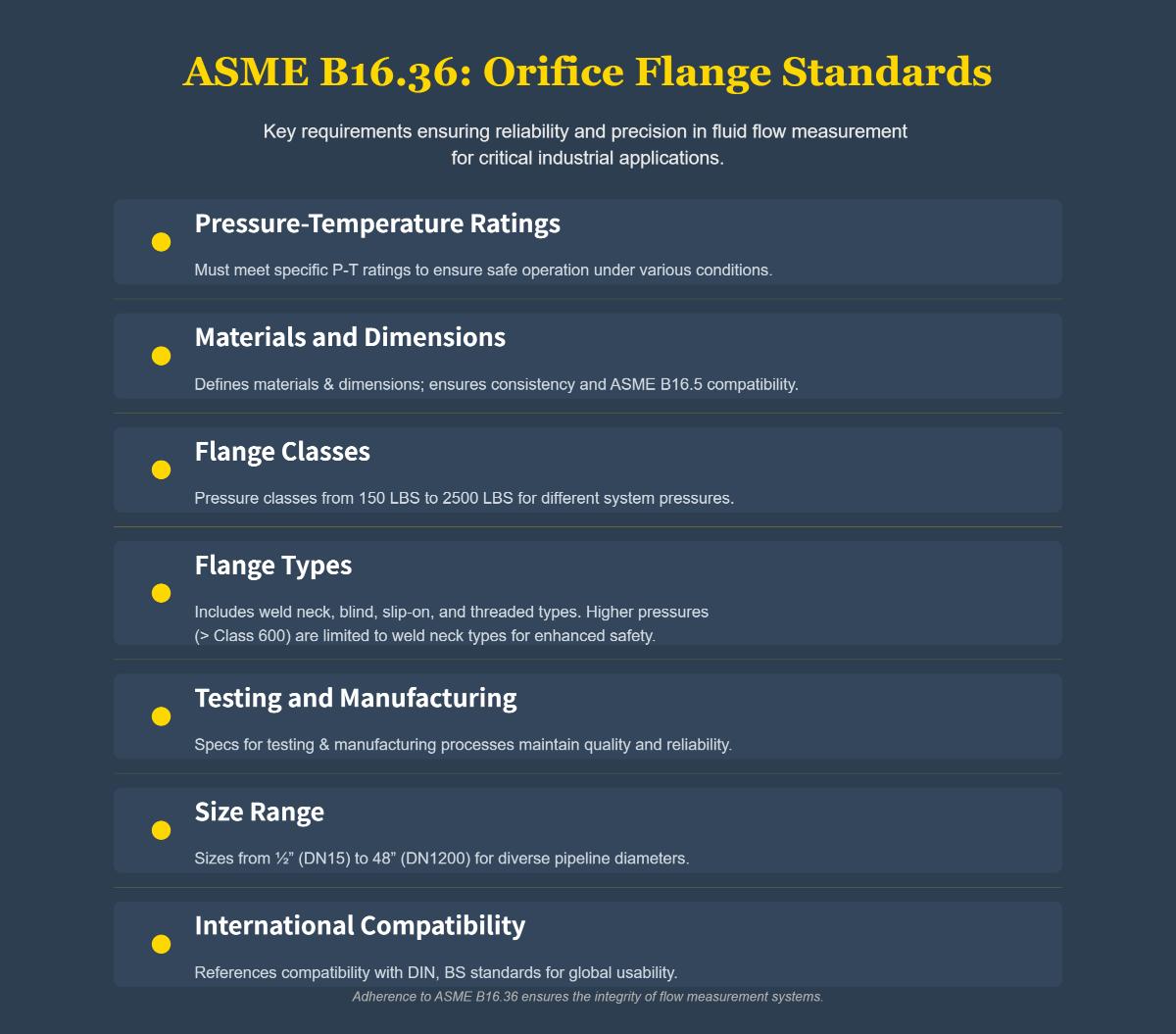
The ASME B16.36 standard specifies the dimensional, material, and manufacturing requirements for orifice flanges. These flanges are essential for measuring fluid flow rates by creating a differential pressure across an orifice plate, and they include pressure tap openings on opposite sides for easy connection to measurement instruments. Designed to integrate seamlessly with pipelines that conform to ASME B16.5 pipe flange standards, orifice flanges are indispensable in various industrial applications.
Following the ASME B16.36 standard is crucial for reliable and accurate flow measurements in industrial applications. This standard provides a comprehensive framework that guarantees the performance and safety of orifice flanges used in measuring fluid flow rates.
Weld neck orifice flanges are designed to be welded directly to the pipe’s neck. This design ensures that the stress from the pressure within the pipe is transferred to the pipe itself, reducing the risk of flange leakage, and is particularly suited for high-pressure systems like those in the oil and gas industry.
Slip-on orifice flanges are slipped over the pipe and welded inside and outside for a secure fit. They are easier to install than weld neck flanges and are typically used in lower-pressure applications.
Threaded orifice flanges screw onto pipes without needing welding, making them ideal for low-pressure systems where welding isn’t feasible.
Orifice unions consist of pairs of flanges that are bolted together with an orifice plate sandwiched in between. They are designed to facilitate the easy insertion and removal of orifice plates using jack screws.
Orifice plates, the key components in orifice flanges, come in various designs to suit different fluid types and flow conditions, including concentric, eccentric, segmental, quadrant, and paddle/universal plates.
Orifice flanges are manufactured from various materials to meet the specific demands of different industrial applications.
Pressure taps are essential parts of orifice flanges that help measure flow accurately by offering points for pressure sensors. These taps are strategically positioned on both sides of the orifice plate to measure the differential pressure created by the flow restriction.
Corner taps are positioned at the edges of the orifice plate and are ideal for smaller diameter pipes. Flange taps, located one pipe diameter upstream and downstream from the orifice plate, are common in larger pipelines. Radius taps, placed one diameter upstream and half a diameter downstream, are used for specific calibration needs.
Orifice plates are central to the functionality of orifice flanges, acting as the primary device that creates a pressure drop to measure flow rates.
Concentric orifice plates have a central bore and are used for clean fluids. Eccentric plates, with an off-center bore, suit fluids with solids. Segmental plates, with a partial bore, are ideal for high-solid-content fluids. Quadrant plates, with a rounded edge bore, work well for viscous fluids.
The orifice plate is a metal disc that creates a controlled restriction, generating a differential pressure across the plate. The size and shape of the bore are tailored to the specific fluid properties and desired flow rate.
Flanges clamp the plate in place and come in various configurations, such as raised-face or ring-type joint (RTJ), to suit different pressure and sealing requirements.
Pressure taps measure upstream and downstream pressures, providing the necessary data to calculate flow rates accurately.
Jack screws make installation and removal easier by allowing the orifice plate to be installed or removed without disassembling the entire pipeline.
Gaskets and bolting ensure a leak-proof seal under high-pressure conditions. These components must be carefully selected to match the flange’s pressure class and material specifications, ensuring compliance with industry standards like ASME B16.36.
To ensure accurate flow measurement, install the orifice plate in a straight section of pipe. The upstream section should be at least five times the pipe’s nominal diameter to minimize turbulence and disturbances that can affect the differential pressure measurement. The downstream section should ideally be at least two times the nominal diameter of the instrument.
The orientation and alignment of the orifice plate are crucial for accurate measurements. The orifice plate must be installed with the “INLET” text facing upstream, and if the bore is beveled, the bevel should face downstream. Precise centering of the orifice plate within the pipe is essential to prevent uneven flow distribution. The orifice bore should be centered within 3% of the inside pipe diameter to avoid significant measurement errors due to disturbed flow profiles.
When assembling the orifice flanges, follow these steps to ensure a proper fit and seal:
Even and controlled tightening of flange bolts is critical to prevent the orifice plate from buckling, which can lead to inaccurate flow measurements. Tighten bolts in a crisscross pattern initially, then secure all studs tightly to prevent distortion. This method ensures even pressure distribution and maintains the integrity of the seal.
Select gaskets that match the pressure class and material specifications of the orifice flanges. Ensure the gaskets are compatible with the operating temperature and pressure conditions to provide a leak-proof seal. Common materials include non-asbestos, PTFE, and spiral wound gaskets, each suitable for different environments.
Design the installation to allow easy access for maintenance and inspection. Consider the placement of jack screws for orifice plate removal and ensure there is enough space around the flanges for tools and personnel. Regular inspection and maintenance are essential to ensure the continued accuracy and reliability of the flow measurement system.
Ensure that the installation complies with relevant standards, such as ASME B16.36, to guarantee safety and compatibility with other system components. Adherence to these standards ensures that the orifice flange assembly will perform reliably under the specified operating conditions.
Improper installation of orifice flanges can significantly disturb the flow profile, leading to major measurement errors. Turbulent flow profiles caused by incorrect installation can severely impact the accuracy of differential pressure measurements.
Solution:
Calibration errors can arise from drift in the instruments over time or from incorrect initial calibration. Such errors can lead to inaccurate flow measurements.
Solution:
Obstructions or blockages within the pipeline can alter the flow profile, leading to erroneous measurements. Debris, sediment, or foreign objects can cause partial blockages that affect the flow rate and pressure readings.
Solution:
Flow disturbances caused by nearby valves, bends, or tees can distort the flow profile, leading to inaccurate measurements. These disturbances can create turbulence that affects the differential pressure readings across the orifice plate.
Solution:
Choosing the appropriate flow meter, including the orifice flange setup, is crucial for accurate flow measurement. Consider factors such as fluid type, pressure, temperature range, and the specific application requirements.
Recommendations:
Maintaining the flow measurement system is essential to ensure long-term accuracy and reliability. Regular cleaning, inspection, and servicing of the components can prevent wear and tear and detect issues early.
Recommendations:
Managing the flow profile is critical to achieving accurate flow measurements. Proper positioning of the orifice flange and using flow conditioning devices can help maintain a stable and laminar flow profile.
Recommendations:
By implementing these troubleshooting strategies and best practices, users can significantly improve the accuracy and reliability of their flow measurement systems. Proper installation, regular maintenance, and careful management of the flow profile are key to achieving precise and consistent measurements.
Choosing the right material for orifice flanges is essential for ensuring their durability, reliability, and performance in various industrial settings. The material must withstand operating conditions, resist corrosion, and be compatible with the media being measured.
The material must be capable of handling the operating pressures and temperatures of the system. Carbon steels (e.g., ASTM A105) are suitable for moderate conditions, while alloy steels (e.g., ASTM A182 F11, F22) are preferred for high-pressure and high-temperature applications. Stainless steels (e.g., ASTM A182 F304, F316) are ideal for high-temperature and high-pressure environments with corrosive elements. Low-alloy steels (e.g., ASTM A350 LF1, LF2) are suitable for low-temperature applications where pressure resistance is still required.
Materials like stainless steel are recommended for environments where corrosion is a concern due to their excellent resistance to various forms of corrosion, including pitting and crevice corrosion.
The selected material must be chemically compatible with the fluid or gas being measured to avoid reactions that could compromise the flange’s integrity or contaminate the media.
Below are answers to some frequently asked questions:
ASME B16.36 specifies the requirements for orifice flanges, which are essential for measuring the flow rate of liquids or gases in pipelines. Key requirements of ASME B16.36 include:
These requirements ensure that orifice flanges are reliable and accurate for fluid flow measurement in various industrial applications.
To properly install orifice flanges for accurate flow measurement, follow these guidelines:
Post-installation, perform leak testing and flow calibration to verify accuracy. Avoid common errors like improper gasket placement, plate distortion, and blocked pressure taps. These steps, aligned with ASME B16.36 standards, help achieve optimal flow measurement accuracy.
For high-pressure orifice flange applications, selecting the appropriate material is critical to ensure safety, reliability, and longevity. The best-suited materials include:
Selecting the correct material based on the specific operational conditions and fluid characteristics is crucial for ensuring the performance and safety of high-pressure orifice flanges. Compliance with ASME B16.36 standards further ensures that the materials used meet the necessary pressure ratings and dimensional requirements for reliable operation.
Flange face configurations significantly affect the performance of orifice flanges by influencing sealing efficiency, pressure handling, and overall system reliability. Various types of flange faces, such as flat face (FF), raised face (RF), and ring-type joint (RTJ), offer distinct advantages depending on the application.
Flat face flanges have a smooth surface and are used with full-face gaskets, ideal for low-pressure and low-temperature environments. Raised face flanges, with a raised sealing surface, concentrate pressure on a smaller gasket area, enhancing sealing performance under moderate to high pressures. Ring-type joint flanges use metal ring gaskets for high sealing performance, suitable for high-pressure and high-temperature environments.
The choice of flange face configuration impacts the type of gasket used, the pressure levels the system can handle, and the compatibility with the materials involved. For instance, FF flanges are preferred for brittle materials like cast iron to avoid stress concentration. Proper selection and application of these configurations, in compliance with ASME B16.36 standards, are essential for optimizing the performance and reliability of the piping system.
Common challenges during orifice flange installation include orientation errors, inadequate flow conditioning, mechanical and design issues, maintenance and calibration gaps, material and compatibility challenges, and compliance with ASME B16.36 standards.
Orientation errors, such as installing the orifice plate backwards, can lead to significant flow measurement inaccuracies. Proper alignment and centering of the plate are crucial to avoid distortion of measurements. Ensuring sufficient straight pipe runs upstream and downstream is essential to minimize turbulence and achieve accurate flow profiles.
Mechanical issues such as undrilled pressure taps, gasket protrusion into the pipe bore, and missing jack screws can complicate installation and affect measurement accuracy. Regular inspection and calibration are necessary to address plate wear and fouling, which can alter the beta ratio and cause measurement drift.
Material selection must consider fluid properties and thermal expansion to prevent degradation and ensure compatibility under varying conditions. Non-compliance with ASME B16.36 standards, including incorrect bore sizing and improper tap spacing, can invalidate measurements and safety certifications.
Mitigation strategies include pre-installation verification, even bolt tightening to prevent plate distortion, and post-installation flow calibration using certified methods. Advanced flange designs and IoT-enabled monitoring are emerging to reduce installation errors and enhance real-time detection of wear.
Orifice plates and pressure taps play crucial roles in flow measurement by creating a measurable pressure drop and allowing for accurate differential pressure readings, respectively. An orifice plate is a thin plate with a specific-sized hole placed perpendicular to the flow in a pipeline, causing a pressure drop proportional to the fluid flow rate. This pressure drop is used to calculate the flow rate based on established equations.
Pressure taps are small openings positioned upstream and downstream of the orifice plate, measuring the pressure difference across the plate. Common configurations include corner taps, flange taps, and D and D/2 taps, each suited for different accuracy and application requirements. These taps ensure precise pressure readings, essential for accurate flow rate calculations. Adhering to ASME B16.36 standards ensures that the orifice flanges and taps are properly designed and installed, maintaining measurement accuracy and system integrity.

