Cast Bronze vs. Bronze: What’s the Difference?
Bronze has long been revered for its strength and versatility, but did you know that not all bronze is created…
Imagine a world where electrical circuits function flawlessly, efficiently powering our homes, industries, and gadgets without a hitch. At the heart of this seamless operation lies the humble copper conductor, a critical component whose ability to carry current can make or break an electrical system. Understanding the current carrying capacity of copper conductors is crucial for anyone involved in electrical design and maintenance. This article delves deep into the factors that influence this capacity, such as ambient temperature, conductor size, and installation conditions. We will also explore the concept of ampacity, how it differs from current carrying capacity, and the pivotal role of the National Electrical Code (NEC) in regulating conductor sizing. Join us as we unravel the intricacies of copper conductors and equip you with the knowledge to make informed decisions in your electrical projects. Ready to dive into the details? Let’s get started.
Copper conductors are electrical wires or cables made from copper, a metal known for its excellent electrical conductivity. These conductors are fundamental components in electrical systems, providing a pathway for the flow of electric current.
Copper has the highest electrical conductivity of all non-precious metals. This is due to its crystal structure and the presence of free electrons, which facilitate the easy flow of electric current. Copper’s electrical resistivity is approximately 16.78 nΩ•m at 20°C, making it highly efficient in minimizing energy loss during transmission.
Copper is highly ductile, meaning it can be stretched into thin wires without breaking. This property is essential for manufacturing cables and wires that need to be flexible yet strong. The combination of ductility and tensile strength allows copper conductors to withstand mechanical stresses during installation and operation.
Copper’s high thermal conductivity helps dissipate the heat generated by electrical resistance. This characteristic is crucial for preventing overheating in electrical systems, ensuring the safe operation of conductors under various load conditions.
Copper’s unique properties make it the preferred choice for electrical wiring and other applications.
Copper conductors are highly reliable, long-lasting, and maintain their conductivity over time while resisting fatigue and corrosion. This reliability reduces the need for frequent maintenance and replacement, making copper a cost-effective option in the long term.
Copper conductors are versatile, suitable for a wide range of electrical applications, from household wiring to industrial power systems. They are compatible with various types of insulation and can be used in both high and low voltage environments.
Safety is another critical factor, as copper’s excellent conductivity and thermal properties reduce the risk of electrical fires caused by overheating. Furthermore, copper conductors are less likely to loosen at connection points due to their creep resistance, ensuring stable and secure electrical connections.
ETP copper is the most common type of copper used in electrical applications. It has a high purity level of at least 99.90% and a conductivity of at least 101% International Annealed Copper Standard (IACS). This type of copper is widely used in power transmission and distribution systems.
Oxygen-free copper is another type, known for its high conductivity and improved thermal stability. It is used in applications where high durability and resistance to oxidation are required, such as in audio and video cables and high-frequency conductors.
In some applications, copper is alloyed with other metals to enhance specific properties. For example, copper-clad aluminum conductors combine copper’s conductivity with aluminum’s light weight, making them ideal for overhead power lines.
Current carrying capacity, or ampacity, is the maximum electric current a conductor can carry before overheating. This ensures the conductor remains within safe temperature limits, preventing damage and hazards like insulation failure or fire.
The size and material of a conductor significantly influence its current carrying capacity. Larger conductors have a greater cross-sectional area, reducing resistance and allowing more current to flow with less heat. Copper, known for its high conductivity, is often used because it efficiently carries electricity with minimal heat generation.
Ambient temperature affects the initial temperature of the conductor. Higher ambient temperatures leave less room for additional heating from current flow, reducing the current carrying capacity. It is important to consider environmental conditions when designing electrical systems.
The type and temperature rating of the insulation around a conductor impact its heat dissipation ability. Insulations with higher temperature ratings enable conductors to carry more current safely. Choosing the right insulation depends on the application and expected operating conditions.
Installation conditions also affect current carrying capacity. Conductors in confined spaces, like conduits or bundles, have restricted heat dissipation, reducing their capacity. Ensuring proper ventilation or cooling can help mitigate this issue and maintain safe operation.
Calculating ampacity involves assessing permissible temperature rises and thermal resistance. Electrical engineers use established formulas and guidelines to determine the safe maximum current a conductor can carry. These calculations help prevent overheating and ensure compliance with safety standards.
International standards, such as those from the National Electrical Code (NEC) and the International Electrotechnical Commission (IEC), provide guidelines for determining current carrying capacities. Adhering to these standards ensures electrical installations are safe, efficient, and compliant with regulations.
Understanding and accurately calculating current carrying capacity is crucial in designing electrical systems, from household wiring to large industrial networks. It ensures systems operate safely and efficiently, preventing potential failures and hazards due to overheating.
Ampacity refers to the maximum electric current a conductor or device can handle without being damaged over time. Expressed in amperes, ampacity is crucial for the safety and efficiency of electrical systems, influenced by factors such as the conductor’s material, size, insulation type, ambient temperature, and installation conditions.
Current carrying capacity is the general ability of a conductor to carry current, whereas ampacity is the maximum current it can handle under specific conditions without overheating. This distinction makes ampacity a more precise measure, considering the conductor’s ability to dissipate heat and avoid overheating.
The main difference between ampacity and current carrying capacity lies in their scope and application:
Several factors affect the ampacity of a copper conductor:
The cross-sectional area of the conductor significantly influences its ampacity. Larger conductors have lower resistance and can carry more current without excessive heating. This is because a larger surface area facilitates better heat dissipation, reducing the risk of overheating.
The surrounding temperature where the conductor is installed affects its ampacity. Higher ambient temperatures reduce the conductor’s ability to dissipate heat, thereby lowering its ampacity. Conversely, lower ambient temperatures allow for higher ampacity as heat can be more effectively dissipated.
Insulation material significantly affects ampacity, as different materials have different temperature limits. For instance, conductors with thermoplastic high-heat-resistant nylon-coated (THHN) insulation have higher temperature tolerances compared to those with polyvinyl chloride (PVC) insulation.
The conditions under which the conductor is installed also impact its ampacity. Conductors installed in free air can dissipate heat more effectively than those enclosed in conduits or buried underground. Proper ventilation and spacing can help maintain optimal ampacity.
When multiple conductors are bundled together, their combined heat generation can affect each conductor’s ampacity. This situation requires derating factors to be applied to ensure safe operation. The National Electrical Code (NEC) provides guidelines for derating based on the number of conductors in a bundle.
Understanding ampacity is crucial for designing safe and efficient electrical systems. Selecting conductors with appropriate ampacity ensures that electrical circuits can handle the expected loads without overheating, which could lead to insulation damage, equipment failure, or fire hazards. Properly sized conductors also improve system reliability and energy efficiency by minimizing voltage drops and energy losses.
Ampacity tables, such as those provided by the NEC, are practical tools for determining the appropriate conductor size for specific applications. These tables list the ampacity ratings for various wire sizes and insulation types under different conditions. Electrical engineers and technicians use these tables to select conductors that meet the required safety and performance standards.
Understanding and applying ampacity ensures that electrical systems are safe, reliable, and efficient, adhering to established guidelines and standards.
The National Electrical Code (NEC), also known as NFPA 70, is a critical standard in the electrical industry, offering detailed guidelines for safely installing electrical wiring and equipment in the U.S. Published by the National Fire Protection Association (NFPA), the NEC is updated every three years to incorporate the latest safety protocols and technological advancements.
The primary purpose of the NEC is to ensure the safe installation and operation of electrical systems. This is achieved by setting minimum safety standards to protect people and property from electrical hazards. The NEC covers various aspects of electrical installations, including wiring methods, conductor sizing, overcurrent protection, grounding, and bonding.
The NEC sets forth detailed safety standards to prevent electrical shocks, fires, and other hazards. These standards are based on extensive research and practical experience, addressing potential risks associated with electrical installations. By adhering to these guidelines, electrical professionals can minimize the likelihood of accidents and ensure a safer environment.
While the NEC itself is not a federal law, it is widely adopted and enforced by state and local jurisdictions across the United States. Compliance with the NEC is often a legal requirement for electrical installations, making it an essential reference for electrical engineers, contractors, and inspectors. Jurisdictions may adopt the NEC in full or with amendments to address specific local needs.
One of the key aspects of the NEC is its regulation of current carrying capacity, also known as ampacity, and the sizing of electrical conductors. Proper conductor sizing is crucial to ensure that electrical systems can handle the expected current loads without overheating, which could lead to insulation failure, equipment damage, or fire hazards.
The NEC provides detailed ampacity tables that specify the maximum current a conductor can carry based on its size (measured in American Wire Gauge, AWG, or thousand circular mils, kcmil) and insulation type. These tables consider the temperature rating of the conductor’s insulation, typically 60°C, 75°C, or 90°C (140°F, 167°F, or 194°F). Conductors with higher temperature ratings can carry more current, making it essential to select the appropriate insulation type for the application.
The ampacity tables are based on an ambient temperature of 30°C (86°F). If the ambient temperature deviates from this baseline, correction factors must be applied to adjust the ampacity accordingly. This ensures that conductors operate safely under varying environmental conditions.
When multiple conductors are bundled together, the heat they generate together requires applying derating factors to prevent overheating. The NEC provides guidelines for derating ampacity based on the number of current-carrying conductors in a bundle and the installation conditions. This helps maintain safe operating temperatures and prevents thermal overload.
Electrical professionals must be well-versed in the NEC to ensure that their installations comply with safety standards and legal requirements. This involves selecting the appropriate conductor size based on the expected current load, insulation type, ambient temperature, and installation conditions. Using the NEC’s ampacity tables and applying the necessary corrections and derating factors are essential for designing safe and efficient electrical systems.
Understanding and adhering to the NEC’s guidelines is fundamental for electrical engineers and contractors. It ensures that electrical installations are not only compliant with safety standards but also optimized for performance and reliability. The NEC continues to evolve, incorporating new technologies and addressing emerging safety concerns, making it an indispensable resource in the electrical industry.
The cross-sectional area of a copper conductor, measured in American Wire Gauge (AWG) or square millimeters (mm²), is crucial for determining its current carrying capacity. Larger conductors have lower electrical resistance, and according to Ohm’s law (V = IR), this allows more current to flow for a given voltage. Moreover, larger conductors offer better heat dissipation. Since heat is generated as a result of the current flowing through the resistance of the conductor, efficient heat dissipation helps to keep the conductor within safe temperature limits. For example, a 10 AWG wire can carry more current than a 14 AWG wire due to its larger cross – sectional area.
Higher ambient temperatures reduce the conductor’s ability to dissipate heat, which lowers its current carrying capacity. Heat transfer occurs from the conductor to its surroundings, and when the surrounding temperature is high, the temperature gradient between the conductor and the environment is reduced. This means that less heat can be transferred away from the conductor. Conversely, in cooler environments, the greater temperature gradient enhances heat dissipation, allowing the conductor to carry more current. For instance, in hot industrial settings, derating factors must be applied to adjust the current carrying capacity to prevent overheating.
Different insulation materials have varying maximum temperature limits, which are essential to prevent damage and electrical hazards. Exceeding these limits can lead to damage of the insulation, which in turn can cause short – circuits or other electrical problems. Materials with higher temperature ratings, such as Polytetrafluoroethylene (PTFE) or silicone, can withstand higher temperatures without degrading. This allows the conductor to carry more current without causing the insulation to break down. Additionally, insulation materials with better thermal conductivity can enhance heat dissipation from the conductor, further preventing overheating.
The method of installing copper conductors affects their current carrying capacity. Conductors installed in free air have better heat dissipation compared to those installed in conduits or confined spaces. In conduits or ducts, the heat generated by the conductor has less room to escape, which reduces the conductor’s ability to dissipate heat. As a result, conductors in these conditions have lower current carrying capacities. However, proper ventilation or the use of cooling methods can mitigate these restrictions and help maintain a relatively higher current carrying capacity.
Bundling multiple copper conductors together can increase their combined heat generation, affecting their ability to dissipate heat effectively. When multiple conductors are bundled together, the internal heat can build up as there is limited surface area for heat dissipation per conductor.
Proper conductor sizing is crucial for the safe and efficient operation of electrical circuits. The primary goal is to select a conductor that can handle the expected current load without overheating or causing a voltage drop that could affect the performance of connected equipment. Several key principles guide the conductor sizing process.
The first step in conductor sizing is to determine the total load that the conductor will carry. This involves calculating the current requirements of all devices and components connected to the circuit, considering both continuous and non-continuous loads, and expressing the total load in amperes (A).
Once the load requirements are known, the appropriate conductor size can be selected using ampacity charts. These charts show the maximum current different conductor sizes and insulation types can handle under various temperatures and installation conditions. Ampacity charts take into account factors such as conductor material, insulation type, and installation conditions.
Ampacity charts are critical tools for selecting the correct conductor size. Follow these steps to use an ampacity chart:
The National Electrical Code (NEC) provides detailed guidelines for conductor sizing to ensure safe and compliant electrical installations. These guidelines include ampacity tables, correction factors for ambient temperature, and derating factors for multiple conductors.
The NEC ampacity tables are based on an ambient temperature of 30°C (86°F). If the actual ambient temperature differs, correction factors must be applied to adjust the ampacity. For example, if the ambient temperature is higher than 30°C, the ampacity of the conductor must be reduced to prevent overheating.
When multiple conductors are installed together, such as in a conduit or cable tray, their combined heat generation can affect their current carrying capacity. The NEC provides derating factors that must be applied to the ampacity based on the number of current-carrying conductors and the installation method.
Suppose you need to size a conductor for a household circuit with a continuous load of 20 amperes. Using an ampacity chart, you might find that a 12 AWG copper conductor with THHN insulation can safely carry 25 amperes at 30°C. After applying any necessary correction factors for ambient temperature or installation conditions, you can confirm that the 12 AWG conductor is appropriate.
For an industrial circuit with a continuous load of 100 amperes, you might select a 3 AWG copper conductor with XHHW insulation. The ampacity chart indicates that this conductor can carry up to 115 amperes at 30°C. Applying correction and derating factors ensures the conductor is sized correctly for the specific installation conditions.
Different types of electrical circuits may have unique requirements that affect conductor sizing. For example:
Energy efficiency is an important consideration in conductor selection. Larger conductors reduce electrical resistance, minimizing energy losses and improving system efficiency. However, this must be balanced with cost and installation constraints.
Selecting the right conductor size involves a comprehensive analysis of load requirements, environmental conditions, and regulatory guidelines. Proper conductor sizing ensures the safe and efficient operation of electrical circuits.
In the past few years, researchers have started actively looking into alternative conductor materials. While traditional materials like copper and aluminum are still widely used, emerging materials present new possibilities. For example, composite conductors are gaining popularity. These conductors often combine different materials to achieve specific properties, such as using carbon fibers or high – strength polymers in combination with metals. Carbon – based conductors, in particular, are being investigated because of their high electrical conductivity and light weight.
Composite conductors offer several advantages over traditional metal conductors. They can be designed for a high strength – to – weight ratio. This ratio is crucial in applications where weight is a concern. Additionally, composite conductors can have better corrosion resistance compared to metals. For instance, a composite conductor with a polymer matrix and embedded metal fibers can resist environmental factors that would normally corrode a pure metal conductor.
Nanostructured conductors are also an area of progress. Manipulating materials at the nanoscale can boost their electrical conductivity. Nanowires, for example, can have unique electrical properties due to their small size and high surface – to – volume ratio. These conductors can be used in high – density integrated circuits and other miniaturized electrical devices.
The future of conductor technology, driven by the need for more energy – efficient and sustainable solutions, is likely to see the development of self – healing conductors. These conductors would be able to repair themselves in case of damage, such as a break or a short – circuit, significantly improving the reliability of electrical systems.
Another area of focus is the integration of smart features into conductors. Smart conductors could monitor their own performance, such as temperature, current, and voltage, and adjust their properties accordingly. This would enable more precise control of electrical systems and prevent failures before they occur.
When it comes to high – speed rail, conductor choice is key for efficient power transmission. In high – speed rail systems, some modern trains use advanced composite conductors. These conductors can handle high currents while being lightweight, which is essential for reducing the energy consumption of the train. The use of these advanced conductors also improves the reliability of the power supply, ensuring smooth operation of the train.
In the realm of renewable energy, conductor efficiency is crucial. Renewable energy systems, such as solar and wind farms, require efficient conductors to transfer the generated electricity. In solar power plants, for example, new types of conductors are being used to reduce energy losses during transmission. Some of these conductors are designed to have low resistance and high heat dissipation capabilities, which are important for maintaining the efficiency of the solar panels.
Below are answers to some frequently asked questions:
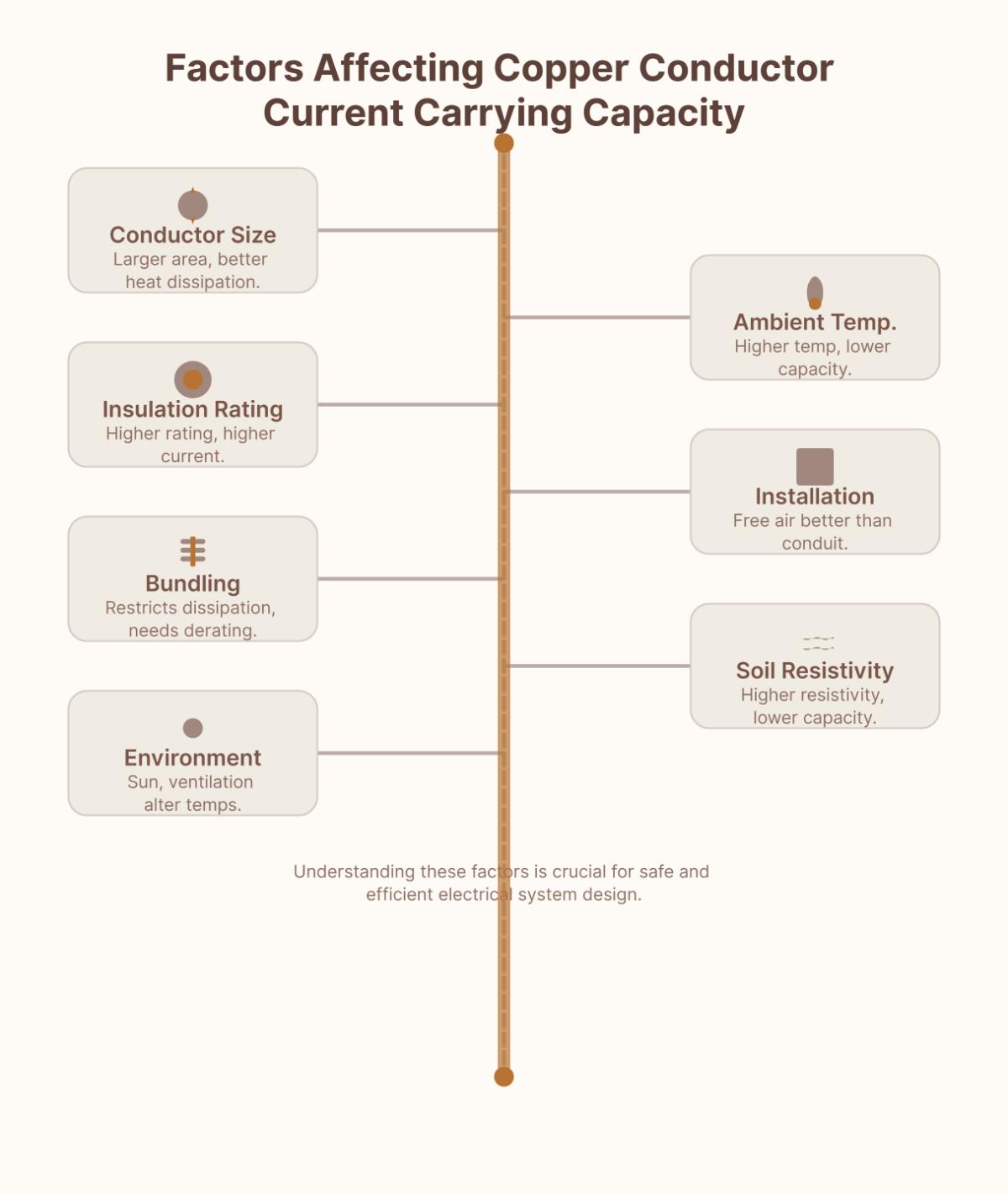
Several factors affect the current carrying capacity of copper conductors. First, the conductor size, particularly its cross-sectional area, is crucial because larger conductors can dissipate heat more effectively and have lower electrical resistance, allowing them to carry more current. Ambient temperature also plays a significant role; higher temperatures reduce the conductor’s capacity due to decreased heat dissipation efficiency. The insulation material’s temperature rating impacts the maximum current a conductor can handle, with higher-rated materials allowing higher current flow. Installation conditions, such as whether the conductor is in free air or enclosed in a conduit, affect heat dissipation. The number of conductors bundled together can also influence capacity, as bundling restricts heat dissipation and necessitates derating. For underground installations, soil thermal resistivity impacts capacity, with higher resistivity reducing it. Lastly, environmental factors like sunlight exposure and ventilation can alter ambient temperatures and thus the conductor’s performance. Understanding these factors ensures safe and efficient electrical system design.
To determine the appropriate wire size for a circuit, you must consider several key factors to ensure safety and efficiency. First, assess the maximum current the circuit will handle, as this dictates the minimum wire gauge needed. Next, evaluate the distance the current will travel, as longer distances can cause voltage drops; typically, a maximum voltage drop of 2% to 5% is acceptable.
Ambient temperature is another critical factor since higher temperatures reduce the current carrying capacity (CCC) of the conductor. Additionally, consider the installation conditions—wires in conduits or bundled together may have reduced CCC. The insulation material of the wire also plays a role because different materials have varying temperature ratings, impacting the CCC.
Using ampacity charts and wire sizing calculators can simplify this process. These tools help match the required current capacity and other factors to the correct wire gauge. Always refer to the National Electrical Code (NEC) for specific guidelines and ensure compliance with local electrical regulations. For complex systems, consulting a qualified electrician or engineer is advisable.
Ampacity and current carrying capacity are related but distinct concepts in electrical engineering. Ampacity refers specifically to the maximum current a conductor can carry continuously without exceeding its temperature rating. This is a crucial measure to prevent overheating and ensure the longevity of the conductor and its insulation. It is determined by factors such as the conductor’s material, insulation type, ambient temperature, and installation conditions.
On the other hand, current carrying capacity is a broader term that encompasses the maximum current a conductor can handle safely without being damaged or compromising its insulation. It considers additional factors beyond those affecting ampacity, such as the conductor’s physical properties and its ability to dissipate heat in various environmental conditions.
NEC compliance is crucial for electrical installations, especially regarding copper conductors. It ensures safety by preventing electrical hazards like fires and shocks through proper conductor sizing and grounding. Legally, it’s often required by local building codes; non – compliance can lead to fines and legal liability. Efficient electrical systems result from NEC – compliant installations, reducing downtime and repair costs. The NEC also helps optimize conductor usage, ensuring copper conductors are used effectively. Additionally, the code is updated regularly to incorporate technological advancements, and working with NEC – knowledgeable electricians further guarantees compliance.
Ambient temperature and installation conditions significantly impact the performance of copper conductors. Higher ambient temperatures reduce heat dissipation, as the smaller temperature difference between the conductor and its surroundings causes the conductor to heat up faster. This decreases the current-carrying capacity, and derating factors are applied to adjust the capacity accordingly. Installation conditions also play a role. Bundling conductors or installing them in confined spaces like conduits reduces heat dissipation, often requiring derating. Poor installation can also compromise insulation integrity, increasing the risk of electrical failures. By considering these factors, engineers can design reliable electrical systems.
Recent advancements in conductor material technology are primarily focused on enhancing the properties of traditional materials like copper and exploring new materials for improved performance. One significant trend is the development of copper-graphene composites, which aim to increase copper’s electrical conductivity by incorporating graphene, a highly conductive form of carbon. This innovation could potentially boost copper’s conductivity by up to 10%.
Another notable trend is the use of the flash process to create more conductive copper wires. This method involves infusing copper with graphene at relatively low temperatures, resulting in enhanced conductivity.
Beyond copper, researchers are exploring transparent conducting oxides with ultra-wide band gap properties, which can improve high-power electronics by allowing faster electron movement while maintaining transparency. Additionally, advancements in proton-conducting materials are being investigated for their potential in green energy technologies like fuel cells and electrolyzers, although these materials currently require high operational temperatures.
Overall, these trends highlight a dual focus on optimizing existing materials and developing new ones to meet the demands of modern electrical and energy applications.

