Strength vs. Stiffness vs. Hardness: Understanding Material Properties
When it comes to engineering and material science, understanding the intricate properties of materials is crucial for designing robust and…
When delving into the world of piping systems, you might encounter the terms DN and PN on flanges and wonder what they signify. These abbreviations are crucial for anyone looking to understand and work with flanges in piping systems. DN stands for “Nominal Diameter” and provides a reference size for the internal diameter of pipes. PN, or “Pressure Nominal,” indicates the pressure capacity the flange can withstand.
In this beginner’s guide, we’ll break down the significance of DN and PN in flange specifications, explore their roles in piping system design, and provide practical insights into selecting the right flanges for various applications. Whether you’re new to the field or looking to refresh your knowledge, this comprehensive technical deep-dive will equip you with the foundational concepts needed to navigate flange selection and application confidently. Ready to demystify DN and PN? Let’s dive in.
In piping systems, two key terms you’ll often encounter are DN (Diameter Nominal) and PN (Pressure Nominal). These terms are essential for specifying and operating pipes and flanges.
Definition: DN, or Diameter Nominal, is a number that represents the approximate internal diameter of a pipe in millimeters. This standard helps ensure compatibility between components from different manufacturers.
Purpose: DN provides a uniform size reference, making it easier to design, select, and assemble compatible piping components.
Comparison with NPS: While DN is used in metric-based countries and follows ISO standards, North America uses Nominal Pipe Size (NPS), which is measured in inches. Although DN and NPS are similar, direct conversions between them are not always exact. For example, DN50 approximately corresponds to a 2-inch NPS pipe, but precise dimensions may vary slightly.
Definition: PN stands for Pressure Nominal and indicates the maximum pressure a pipe or flange can handle, measured in bars at 20°C.
Purpose: PN values are critical for ensuring that piping components can handle the operational pressures they will encounter. This rating helps in selecting the appropriate components that can safely and efficiently manage the system’s pressure. For example, a PN16 rating means the component can endure up to 16 bars of pressure.
Pressure Ratings and Temperature: PN ratings come in a series of standard values such as PN10, PN16, and PN25. These ratings are influenced by temperature; higher temperatures typically reduce the maximum allowable pressure, necessitating adjustments to maintain safety.
| Aspect | DN (Diameter Nominal) | PN (Pressure Nominal) |
|---|---|---|
| Definition | Indicates internal pipe diameter, measured in millimeters | Indicates maximum pressure capacity, measured in bars |
Application: Understanding DN and PN is essential for engineers and technicians to design and maintain piping systems that function safely and efficiently. Mismatching DN and PN can lead to system failures, leaks, or even catastrophic failures.
Conversion and Compatibility: While there are equivalencies between DN/PN and ANSI/NPS systems, direct conversion is not always straightforward. Engineers often need to use adapters or conversion charts to ensure compatibility when mixing components from different standards.
Understanding DN (Diameter Nominal) and PN (Pressure Nominal) is essential for matching flange specifications. Flanges are integral components in piping systems, connecting pipes and other equipment to ensure a secure and leak-proof system. The DN value represents the nominal diameter, standardizing the size reference for pipes and flanges, facilitating the matching of components from different manufacturers. This standardization is crucial in international projects where components might be sourced globally. Ensuring that flanges and pipes have matching DN values is vital to maintain system integrity and prevent leaks.
Safety is a paramount consideration in piping system design and operation. The PN rating indicates the maximum pressure a flange can safely withstand at a specified temperature, measured in bars. Selecting flanges with appropriate PN ratings ensures that they can handle the operational pressures safely. For instance, a PN 16 flange can sustain up to 16 bars of pressure, making it suitable for various industrial applications. Using a flange with an inadequate PN rating can lead to system failures, posing significant safety risks, including leaks, bursts, and potential harm to personnel and equipment.
Efficiency in piping systems is closely linked to the correct specification of DN and PN values, which ensure consistent internal diameters and appropriate pressure handling. Proper DN sizing optimizes fluid flow characteristics, minimizing pressure drops and turbulence. This uniformity is critical in maintaining the desired flow rates and reducing energy consumption in pumping systems. Similarly, selecting the correct PN rating prevents over-specifying components, which can lead to unnecessary costs. Efficiently designed systems, with appropriately rated flanges, contribute to In industrial piping systems, adherence to international standards such as ISO, DIN, and EN is essential for regulatory compliance and operational efficiency. DN and PN values are part of these standards, ensuring that components meet specific design and safety criteria. Using standardized flanges simplifies the design and maintenance processes, as engineers can reliably source components that are guaranteed to be compatible and safe. Compliance with these standards also streamlines inspections and approvals, reducing regulatory risks.
Flanges with specified DN and PN ratings are versatile and can be used in a wide range of applications, from low-pressure water treatment systems to high-pressure oil and gas pipelines. The variety of DN sizes and PN ratings allows engineers to select flanges that meet specific operational requirements, ensuring safety and efficiency in diverse environments. This versatility is crucial for engineers to design systems that meet specific operational requirements while maintaining safety and efficiency.
Standardized DN and PN values also simplify maintenance and repairs in piping systems. When components need replacement, having standardized sizes and pressure ratings ensures that new parts will fit seamlessly with existing systems, minimizing downtime and labor costs. This standardization also allows for the stocking of common replacement parts, enhancing the readiness for quick repairs and reducing the need for custom manufacturing, which can be time-consuming and expensive.
In piping system design, DN (Diameter Nominal) and PN (Pressure Nominal) are crucial for selecting and operating components like pipes, valves, and fittings correctly.
Standardization and Compatibility
DN represents the nominal internal diameter of pipes and fittings, standardized in millimeters. This dimensionless number helps engineers and designers specify and select components that fit together seamlessly, regardless of the manufacturer. Using DN values ensures that components from different suppliers can be combined without compatibility issues, simplifying the design process and reducing the risk of mismatched parts.
Example of DN Application
In a building’s water distribution system, using DN values ensures that all components, like a DN50 valve, fit together properly, allowing smooth fluid flow and easy installation.
Pressure Handling Capability
PN shows the maximum pressure a component can handle at a specific temperature, usually 20°C, and is measured in bars. Selecting components with the appropriate PN rating ensures that the system can safely handle the operational pressures without risk of failure.
Ensuring System Integrity
Using the correct PN rating is critical in maintaining the integrity of the piping system. For instance, a PN16 rating means that the component can handle up to 16 bars of pressure, ensuring that the system can operate safely under the specified conditions, preventing leaks or bursts.
Example of PN Application
In an industrial setting where high-pressure steam is transported, selecting pipes and flanges with an appropriate PN rating, such as PN25, ensures that the system can manage the high pressures involved. This selection is vital for the safety and reliability of the operation.
Matching DN and PN
When designing a piping system, it is crucial to match DN and PN values appropriately. A DN100 pipe with a PN16 rating indicates a pipe that has an internal diameter of approximately 100 mm and can withstand a pressure of 16 bars. This combination ensures that the pipe fits correctly within the system and can handle the required pressure.
Design Considerations
Engineers must consider both the size and pressure requirements of the system. For example, a system transporting high-temperature fluids may require components with higher PN ratings to account for the reduced pressure handling capacity at elevated temperatures. Similarly, the DN value must be chosen to ensure adequate flow rates and minimal pressure drops.
Industrial Applications
In industries such as oil and gas, chemical processing, and water treatment, DN and PN values are used to specify components that meet stringent operational requirements. For example, in a chemical plant, pipes with DN150 and PN25 ratings might be used to transport corrosive chemicals under high pressure, ensuring both safety and efficiency.
Infrastructure Projects
In large infrastructure projects like municipal water systems, standardized DN and PN values ensure components from different suppliers fit together, which is vital for system reliability and maintenance.
Flanges are essential in connecting pipes and equipment within a piping system, allowing for easy assembly and disassembly. This makes maintenance and modifications more straightforward, especially in systems requiring regular inspections or cleaning.
Slip-on flanges are easy to install and often used in low-pressure systems that require quick assembly and disassembly.
Weld neck flanges, with their long, tapered hub, offer increased strength and resistance, making them ideal for high-pressure applications like those in the oil and gas industry.
Blind flanges close the end of a piping system or vessel opening, crucial for pressure testing and maintenance by isolating sections of the system.
Socket weld flanges are used for small-diameter, high-pressure pipes. The pipe is inserted into the socket end and then welded around the top, providing a strong and leak-proof connection.
Lap joint flanges consist of two components: a stub end and a loose backing flange. This design allows for easy alignment and is often used in systems that require frequent dismantling and inspection.
Threaded flanges are used in systems where welding is not feasible. They are screwed onto the pipe and are suitable for low-pressure, non-critical applications.
Flanges are designed to handle various pressures and temperatures, making them versatile components in piping systems. Selecting the appropriate flange type and material is crucial to ensure the system can operate safely under the expected conditions. For example, high-pressure systems such as steam lines often use weld neck flanges, while lower pressure systems might use slip-on or threaded flanges.
In the petrochemical industry, flanges connect pipelines for transporting hazardous materials. In water treatment systems, flanges link pipes, valves, and pumps, allowing easy access for maintenance. In power plants, flanges join components like boilers and turbines, suitable for high-pressure and high-temperature environments.
Flanges are indispensable components in piping systems, providing secure connections, facilitating maintenance, and ensuring the safe operation of the system under various conditions. Their versatility and ease of use make them a preferred choice in many industrial applications.
Pressure rating is a crucial factor when choosing flanges for piping systems, as it indicates the maximum pressure a flange can safely endure at a specific temperature. This ensures that the flange can operate effectively under the designated working conditions without risk of failure.
The ASME/ANSI system, commonly used in North America, categorizes flanges into pressure classes such as Class 150, 300, 400, 600, 900, 1500, and 2500. These classes represent the maximum allowable working pressure in pounds per square inch (psi) at a specified temperature, usually 100°F (38°C). For instance, a Class 150 flange can handle up to 150 psi at 100°F.
In European and international standards, the DN (Diameter Nominal) and PN (Pressure Nominal) system is prevalent. DN represents the nominal diameter of the pipe or flange, while PN indicates the nominal pressure rating in bars. Common PN ratings include PN10, PN16, and PN25, corresponding to 10, 16, and 25 bars of pressure, respectively.
The pressure-handling capacity of flanges decreases as the operating temperature rises. Therefore, it’s crucial to choose a flange that can handle both the pressure and temperature conditions it will face. For example, a flange rated for 150 psi at 100°F might only handle 75 psi at 300°F.
Different materials have varying pressure-temperature ratings. For example, stainless steel flanges typically have higher ratings than carbon steel flanges at the same temperature. Additionally, flanges must be compatible with other system components; ASME/ANSI and DN/PN flanges are not interchangeable due to differences in dimensions, materials, and pressure ratings. Ensuring compatibility is vital for system integrity and safety.
Selecting the appropriate flange class is essential for applications requiring specific pressure resistance. For example, in a high-pressure system demanding 800 psi at 500°F, a Class 400 flange would be appropriate. Conversely, lower pressure applications might only require a Class 150 flange.
When using flanges with different pressure ratings in the same system, the maximum pressure rating of the entire system will be limited by the lowest-rated component, ensuring that no part of the system is exposed to pressures beyond its capacity. This precaution maintains safety and functionality across the entire system.
DN stands for Diameter Nominal, representing the nominal diameter of a pipe or flange in millimeters. This measurement ensures compatibility between components from different manufacturers, facilitating easy assembly and maintenance.
PN denotes Pressure Nominal and indicates the maximum pressure a pipe or flange can withstand, measured in bars. This rating is critical for ensuring the safety and efficiency of the piping system, as it helps in selecting components that can handle the required operational pressures.
Weld neck flanges are valued for their strength and stress-reducing design. They are ideal for high-pressure and high-temperature applications, such as in the oil and gas industry.
Slip-on flanges are easy to install and cost-effective. They fit over the pipe and are welded in place, making them suitable for low-pressure applications.
Lap joint flanges, consisting of a stub end and a backing flange, are used in systems requiring frequent dismantling for easy alignment and assembly.
Threaded flanges are screwed onto the pipe without welding, making them ideal for small-diameter applications where welding is not practical.
Blind flanges are used to close off the ends of piping systems, providing easy access for maintenance and pressure testing.
Raised face flanges have a small raised section around the bore, which provides a gasket seating surface. They are commonly used in a wide range of applications.
Ring type joint flanges are used in high-pressure and high-temperature applications. They feature a metal gasket seated in a groove, providing a strong seal.
Flat face flanges have a flat gasket seating surface, making full contact with the gasket. They are typically used in low-pressure applications.
These flange designs feature matching raised sections and recesses, which help with self-alignment and provide a reservoir for gasket adhesive, ensuring a tight seal.
Flanges are categorized into pressure classes that indicate their maximum allowable pressure. Common classes include 150#, 300#, 600#, 900#, 1500#, and 2500#. Higher classes indicate the flange can handle greater pressure.
Flanges are made from various materials, such as carbon steel, stainless steel, and ductile iron. The choice of material depends on factors like corrosion resistance, temperature, and pressure requirements.
Flanges must comply with specific standards, such as ASME B16.5 or ISO 7005, which dictate their dimensions and material requirements. Adhering to these standards ensures that the flanges will perform reliably in their intended applications.
When integrating components, it’s crucial to ensure that DN and PN ratings match. This ensures compatibility and prevents issues that could arise from mixing components with different ratings. Adapters may be necessary when interfacing components with different standards, such as ASME/NPS and ISO/DIN.
The International Organization for Standardization (ISO) creates and publishes global standards to ensure quality, safety, and efficiency in various industries. ISO flange standards, such as ISO 7005, harmonize specifications globally, making it easier for manufacturers and engineers to source and use compatible components.
ISO 7005 is a comprehensive standard covering flanges made from materials like steel, cast iron, copper alloys, and composites. It uses the PN (Pressure Nominal) rating system to indicate the maximum pressure a flange can handle at room temperature, measured in bars. This standardization helps ensure that flanges can be used interchangeably in international projects.
DIN standards are widely used in Germany and other European countries. However, they are being gradually replaced by EN standards.
These standards utilize metric measurements and the PN rating system, ensuring that flanges can handle specified pressures at room temperature.
European Norms (EN) are standards developed by the European Committee for Standardization (CEN) to unify standards across Europe. EN standards have largely replaced DIN standards, providing a cohesive framework for flange specifications that are recognized throughout the European Union.
EN 1092-1 is a widely used European standard for steel flanges. It includes requirements for dimensions, pressure ratings, and materials, using the DN (Diameter Nominal) and PN (Pressure Nominal) system.
In Europe and Asia, DN and PN are common, while North America uses ANSI/ASME standards. Ensuring compatibility between flanges and pipes is crucial to avoid misalignment and ensure safety and efficiency.
Below are answers to some frequently asked questions:
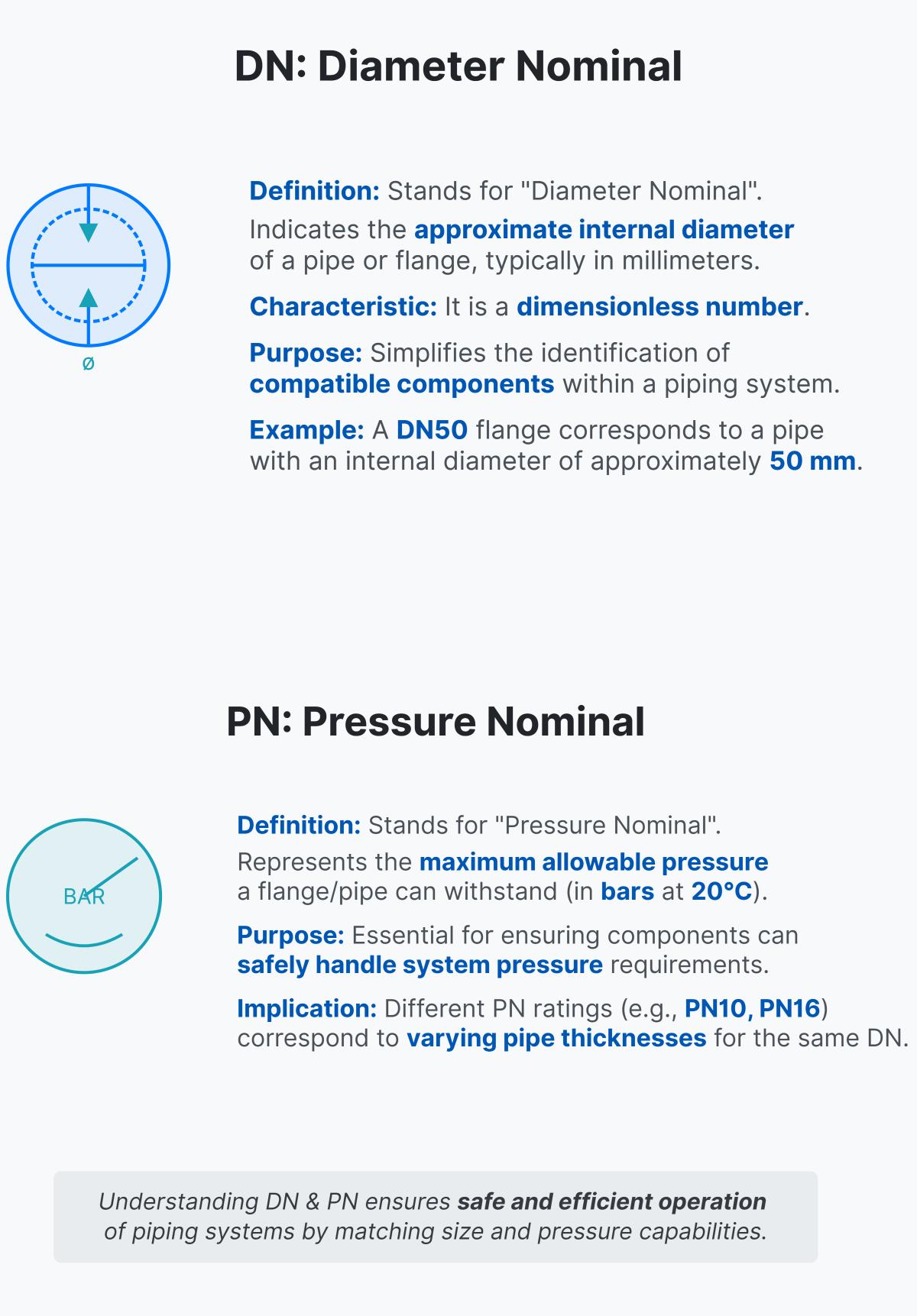
DN and PN are critical terms used in the specification of flanges in piping systems. DN stands for “Diameter Nominal” and indicates the approximate internal diameter of a pipe or flange in millimeters. It is a dimensionless number, simplifying the identification of compatible components within a piping system. For example, a DN50 flange corresponds to a pipe with an internal diameter of approximately 50 mm.
PN stands for “Pressure Nominal” and represents the maximum allowable pressure a flange or pipe can withstand, measured in bars at a reference temperature of 20°C. PN ratings, such as PN10 or PN16, are essential for ensuring that piping components can safely handle the specific pressure requirements of a system. Different PN ratings correspond to varying pipe thicknesses for the same DN.
Understanding DN and PN helps ensure the safe and efficient operation of piping systems by matching the correct size and pressure capabilities to the system’s requirements.
In piping system design, DN (Diameter Nominal) and PN (Pressure Nominal) are essential for specifying the dimensions and pressure ratings of pipes, valves, and fittings, ensuring compatibility and safety.
DN indicates the approximate internal diameter of pipes and fittings in millimeters, simplifying the selection process by standardizing pipe sizes. For instance, DN50 corresponds to a pipe with an internal diameter of roughly 50 mm. This helps engineers choose the right pipe diameter to ensure proper fluid flow and material compatibility.
PN represents the maximum allowable pressure a component can handle, measured in bars at a reference temperature of 20°C. For example, PN16 indicates that a flange can withstand up to 16 bars of pressure. This rating is crucial for selecting components that can safely operate under expected pressure conditions, preventing system failures and optimizing cost efficiency.
By understanding and applying DN and PN standards, engineers can design piping systems that are reliable, safe, and efficient, ensuring all components work together seamlessly.
DN (Diameter Nominal) and PN (Pressure Nominal) are essential terms used in the specification of flanges and piping systems. DN refers to the size of a pipe or flange based on its internal diameter and is measured in millimeters. For example, a DN50 pipe typically has an internal diameter close to 50 mm. PN, on the other hand, indicates the pressure rating of a pipe or flange, specifying the maximum pressure it can handle at a given temperature, usually measured in bars. Common PN ratings include PN6, PN10, PN16, PN25, and PN40.
The key difference between DN and PN lies in their focus: DN relates to the physical dimensions (size) of the pipe, while PN pertains to the operational safety by defining the pressure capacity. Both parameters are crucial for ensuring the compatibility and safety of components within a piping system.
Selecting the appropriate flange for your piping system involves several important steps. First, you need to determine the nominal diameter (DN) and the pressure rating (PN) required for your system. DN refers to the nominal diameter of the pipe, which ensures compatibility with other components. PN indicates the maximum pressure the flange can handle, measured in bars.
Next, consider the type of flange that suits your application. Common types include weld neck flanges for high-pressure environments, slip-on flanges for ease of installation, and blind flanges for sealing pipe ends.
Material selection is also crucial. Carbon steel is commonly used for general purposes, while stainless steel is preferred for corrosive environments. Specialty metals may be required for high-temperature or chemically resistant applications.
Additionally, ensure the flange meets relevant standards such as ASME, ANSI, or DIN, and verify that its dimensions match the pipes and fittings in your system.
By carefully considering these factors—DN, PN, flange type, material, and standards compliance—you can select the appropriate flange to ensure safety, efficiency, and reliability in your piping system.
The common standards for flanges in piping systems are essential guidelines that ensure the compatibility and safety of components within a piping network. These standards include:
Understanding these standards helps ensure that the selected flanges will fit correctly and perform reliably within a given piping system.
Pressure rating is crucial in flange selection as it specifies the maximum pressure a flange can safely withstand at a given temperature. This ensures the piping system operates safely and reliably. Higher pressure ratings indicate that the flange can handle greater pressures. The material of the flange also affects its pressure rating, with different materials having different strengths at the same temperature. For example, stainless steel typically has a higher pressure rating than carbon steel. Selecting a flange with the correct pressure rating is essential to match the system’s design conditions and comply with industry standards like ASME B16.5, ensuring safety and preventing leaks or failures.

